
Quick answer: Choose a synchronous high-frequency welding and cutting machine when the product needs an accurately aligned HF seam and finished edge in one controlled tooling cycle. Approval should come from production-material trials that prove edge quality, weld strength, appearance, tool life, safe scrap removal, and stable output—not from machine power alone.
Terminology: High-frequency (HF) welding is also known as radio-frequency (RF) welding. In this guide, HF refers to the plastic welding process.
When Does Synchronous HF Welding and Cutting Make Sense?
| Production need | Integrated weld-and-cut value | What must be tested |
|---|---|---|
| Close edge-to-seam position | One tool can keep the cutting path registered to the welded shape. | Edge distance, corner quality, and dimensional repeatability |
| Fewer handling steps | The part may leave the station with less secondary trimming. | Safe unloading, scrap separation, and actual labor time |
| Decorative embossed edge | Welding, embossing, and cutting features can share a tool concept. | Surface marks, pattern definition, and bond strength |
| Repeat production | Dedicated tooling can support a consistent part family. | Material variation, tool wear, changeover, and maintenance |
| Higher output target | Two stations can overlap operator loading and machine processing. | Balanced station work and a complete cycle-time study |
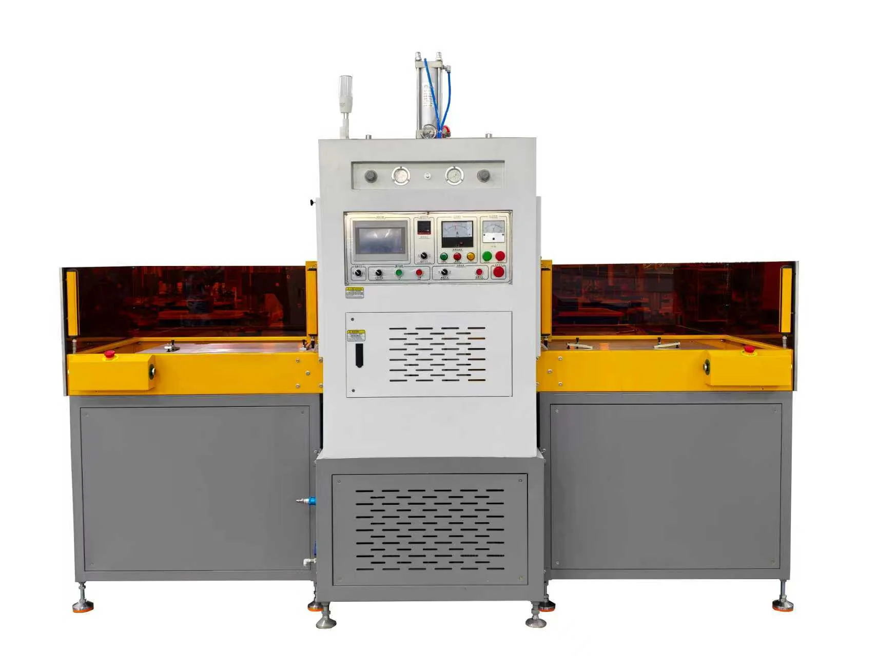
A synchronous high-frequency welding and cutting machine combines dielectric heating, press force, and a shaped tool so that joining and edge cutting remain accurately related. It is often considered for flexible products, coated fabrics, shoe components, embossed panels, protective products, and other parts where a secondary trimming step would add alignment work.
Application requirements still differ. Buyers working with controlled seals should review the HF welding machine guide for medical products. Buyers focused on visible trim should use the high-frequency welding guide for automotive interiors.
“Synchronous” does not mean that every material can be welded and cut successfully at exactly the same instant. Tool construction and control sequence vary. Some designs use staged pressure or a controlled difference between welding and cutting features. Therefore, buyers should describe the required finished edge and allow the supplier to propose a tested sequence.
If your product only needs an HF seam, a simpler press may cost less and be easier to maintain. Begin with the high-frequency welding equipment buyer’s guide if you are still deciding between standard welding, embossing, and integrated weld-and-cut equipment.
Material Compatibility Comes Before Tool Design
HF heating works with dielectric materials that respond to a high-frequency electric field. PVC and many TPU formulations are common examples. Some coated fabrics and laminated constructions can also be suitable. Yet a familiar resin name does not guarantee a good result. Pigment, plasticizer, fabric, foam, adhesive, coating, moisture, and thickness all affect heating and pressure transfer.
The cutting step adds another requirement. The stack must separate cleanly without dragging, excessive fuzz, melted debris, or damage to the welded edge. A fabric backing may behave very differently from a film. Thick foam can spring back. A reinforcement layer can stop or divert the cutting feature. This is why a trial must use the full production stack.
Send these materials for the first trial
- Production-grade sheets or cut blanks from each approved supplier
- Every backing, foam, fabric, film, adhesive, ink, and reinforcement
- Parts conditioned as they will be before production
- A drawing showing weld width, cut line, corners, holes, and critical surfaces
- Accepted finished samples and rejected samples when available
A supplier should not promise output or edge quality from a photograph. The practical result depends on effective weld area, total cut length, material response, pressure distribution, and the finished-part tolerance.
How the Weld-and-Cut Tool Affects Quality
The tool must heat and press the weld zone while creating the required edge. Small differences in tool height can change which feature contacts first. If a cutting feature acts too early, it may interrupt energy flow or distort the seam. If it acts too late, the edge may stretch or remain partly connected. Corners and narrow bridges need special attention because energy can concentrate there.
The lower fixture also matters. It supports the stack, keeps layers registered, and provides a stable surface for the cutting action. It may need replaceable pads or inserts in high-wear areas. The maintenance plan should explain how operators inspect the tool, remove debris, check alignment, and replace wear parts.
Practical rule: A successful weld-and-cut process is a matched system: material, electrode, cutting feature, support fixture, pressure, HF tuning, cooling, and removal all work together.
Ask the trial team to inspect the complete perimeter, not only a straight section. Rounded corners, sharp corners, starts and stops, thick overlaps, and reinforced areas often reveal problems first. If the part includes printing or a visible grain, confirm registration and surface appearance under normal viewing light.
What Quality Checks Should Be in the Sample Report?
Quality checks should follow the function of the finished part. A decorative component may prioritize edge definition, emboss depth, color, gloss, and dimensions. A sealed component may also need peel, tensile, leak, burst, or ageing tests. The buyer must provide the test method and pass limit.
The sample report should identify the material lot, layer direction, tooling version, principal settings, and result. It should also note any arcing, sticking, scrap-removal problem, or visible mark. Several settings should be explored to find a usable process window. One attractive sample at one setting is not enough evidence for stable production.
Recommended acceptance points
- Weld width and distance from the final cut edge
- Bond strength or leak performance required by the product
- Complete edge separation with no unwanted tags
- Dimensions, flatness, and distortion after cooling
- Allowed marks, thinning, flash, scorching, or gloss change
- Scrap removal and safe unloading method
- Performance after an agreed number of repeated cycles
Single Station, Sliding Table, or Dual Station?
A single station can be appropriate for lower volume, frequent product changes, or complex manual loading. A sliding table moves the fixture between the operator and protected processing position. A dual-station design can allow one fixture to be loaded while the other is processed, depending on the machine’s guarding and control sequence.
More stations do not guarantee more good parts. The operator may still need time to align several layers, remove internal scrap, inspect the edge, and handle warm components. A realistic time study should include every task. Compare station concepts by timing the complete loading, processing, cooling, unloading, and inspection sequence.
For equipment using left/right or front/rear moving fixtures, the sliding-table high-frequency embossing and fusing machine guide gives additional selection points.
Tuning and Spark Protection
Tool geometry and material load change the electrical behavior of the welding system. The machine must be tuned for the actual part and electrode. Incorrect tuning, contamination, uneven contact, sharp tool features, or too much energy can increase the risk of arcing.
A spark-protection system can detect an abnormal condition and interrupt energy to reduce damage. It is an important safeguard, but it does not remove the need for clean material, smooth tooling, correct setup, and routine inspection. Repeated alarms require a root-cause review before production continues.
Prepare a Complete Request for Quotation
To select the press, generator, table, fixture, control sequence, and guarding, Jfortune needs more than a product name. Send:
- Exact material grade and supplier for every layer
- Full layer structure, thickness, coating, adhesive, and reinforcement
- Weld-seam and cut-line drawing with all critical dimensions
- Overall part dimensions, orientation, and required loading access
- Estimated electrode or mold area and total cutting path
- Good-parts output per hour or per shift
- Quality test methods, limits, appearance sample, and traceability needs
- Destination voltage, frequency, compressed air, language, and safety requirements
Frequently Asked Questions
Can the machine weld, emboss, and cut in one cycle?
It may be possible with compatible material and correctly designed tooling. The sequence and feature heights must be developed through trials. Finished appearance, strength, edge separation, and tool wear all need approval.
Will integrated cutting eliminate every secondary operation?
Not always. Some products still need internal scrap removal, inspection, hole clearing, cleaning, or final trimming. The quotation should define exactly which operations occur inside and outside the machine.
Is a dual-station machine always faster?
No. It helps when operator loading and unloading can overlap machine processing. Output still depends on layer alignment, scrap handling, cooling, inspection, and station balance. Use a complete time study.
Can one tool run several material suppliers?
The physical tool may fit, but the welding window can change with material formulation and thickness. Each approved material source should be tested and documented before production release.
Get a Weld-and-Cut Process Review
Send the part before you select the machine. Provide Jfortune with the material grade, complete layer structure, weld-and-cut drawing, part dimensions, estimated mold area, target output, quality standard, and destination power and safety requirements. Add production-grade samples whenever possible. The engineering team can review weldability, tooling, station flow, controls, and a practical trial plan.
Request a Weld-and-Cut Process Review
Technical Reference
- TWI: High Frequency Welding Handbook — process fundamentals for dielectric heating, materials and electrodes.
 EN
EN  DE
DE  ES
ES  PT
PT  RU
RU  JA
JA  IT
IT  AR
AR  KO
KO