
A sliding table high frequency embossing machine moves the loaded fixture between an accessible loading position and a guarded HF press position. With the correct electrode, it can emboss a decorative pattern, weld compatible layers, or combine fusing and perimeter cutting. The process must be qualified with the exact material stack and appearance requirement.
Terminology: High-frequency (HF) welding is also known as radio-frequency (RF) welding. In this guide, HF refers to the plastic welding process.
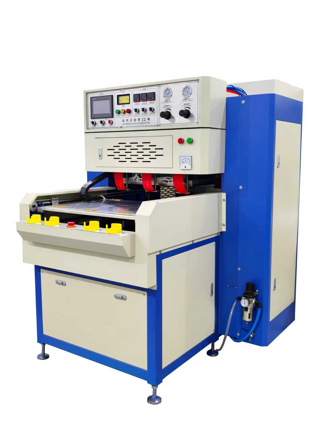
Sliding-Table HF Embossing at a Glance
- Process: dielectric heating plus pressure through a shaped electrode
- Typical work: shoe uppers, logos, bag panels, coated textiles and decorative plastic layers
- Table value: loads outside the press zone and locates the fixture for the controlled cycle
- Critical tooling: electrode profile, depth stops, lower insulation, alignment and surface protection
- Acceptance: appearance, bond strength, cut edge and repeatability across the complete tool
Embossing, Welding and Fusing Are Different Results
Embossing forms a raised or recessed design in the surface. Welding creates a molecular bond between compatible layers. Fusing is often used as a general term for joining and may include a cutting edge that separates the finished outline. A single tool can combine these effects, but each area has a different function and energy density.
The drawing should therefore identify decorative zones, structural welds, trim edges and “no mark” surfaces separately. If the supplier sees only an outside product photo, it cannot reliably determine electrode width, stop height, expected depth or inspection method.
How the Sliding Table Changes the Work Cycle
The fixture is loaded at the front or side of the machine, away from the upper electrode. The table then moves to a repeatable process position. Interlocks confirm that the table and guard are in the approved state before the press descends and HF energy is enabled. After welding and cooling, the head returns and the table presents the part for unloading.
This arrangement improves access for larger flexible components and keeps hands away from the HF press area during the cycle. Front/rear designs use one moving table path; left/right systems can support alternating stations. The choice depends on product size, operator movement, footprint and whether loading time can overlap the machine cycle.
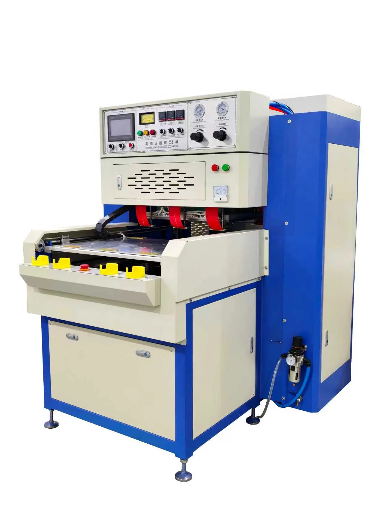
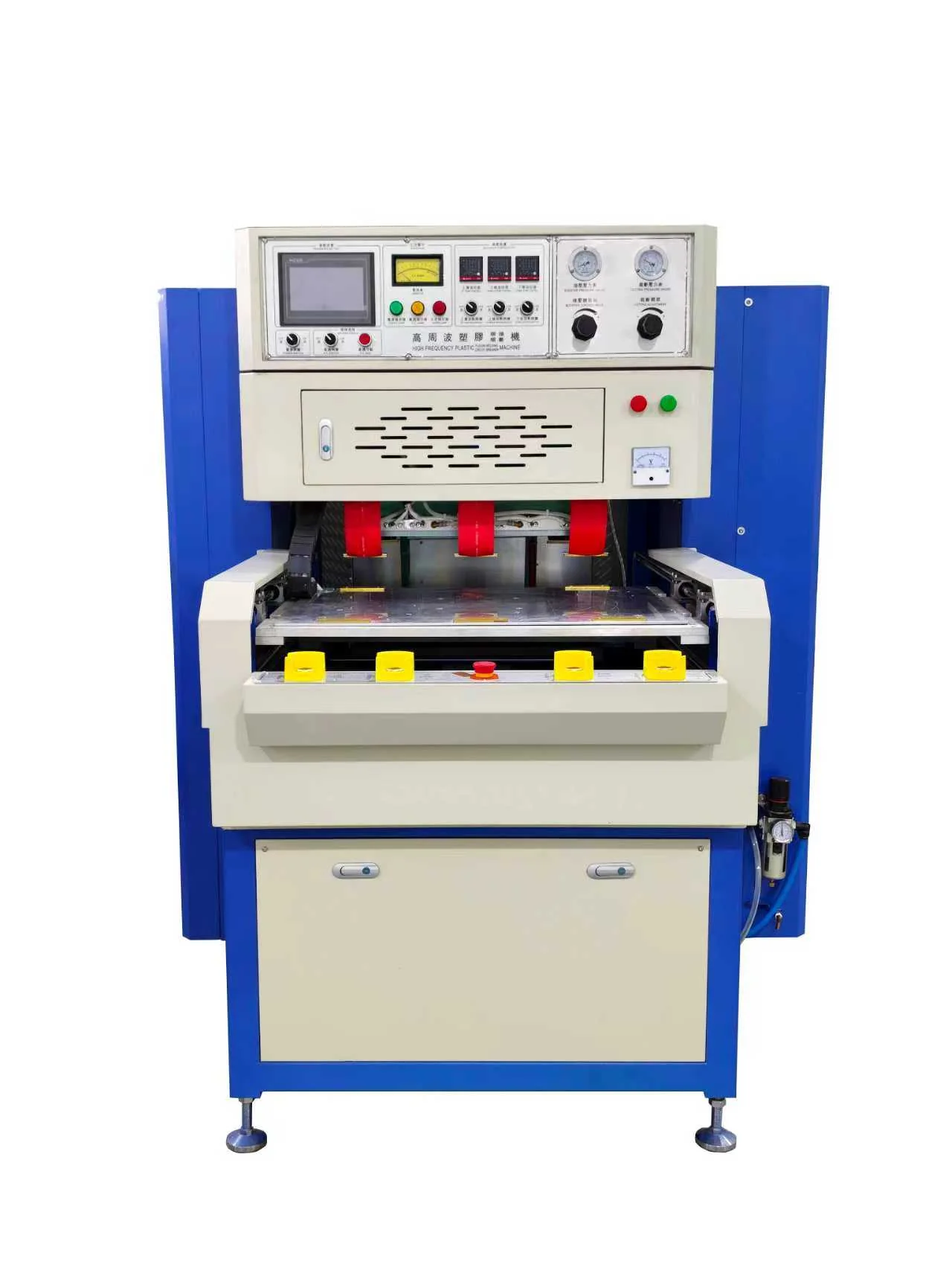
Continue Your Sliding-Table Equipment Review
- Rotary-table vs sliding-table HF machine comparison
- Synchronous high-frequency welding and cutting guide
- 27.12 MHz tuning and spark protection guide
Send material data and a part drawing for a Jfortune process review.
Material Stack and Surface Appearance
Footwear and bag components may combine a face film, foam, fabric backing, printed layer, reinforcement and adhesive. The HF field does not heat every layer equally. A face material may show a clear pattern while the backing overheats, or a thick foam may collapse before the weld reaches strength.
Jfortune requests the released construction and representative samples, including color variants and normal thickness tolerance. Trials should use the intended decoration, printing and surface treatment. For appearance-sensitive work, agree on gloss change, color shift, edge flash, pattern definition and permitted witness marks under defined lighting.
Electrode Design for Detailed Embossing
The electrode face reproduces the pattern and concentrates the HF field. Fine lines need enough strength and release clearance to survive production cleaning. Broad areas need balanced pressure and field distribution. Sharp transitions can increase local energy density and arc risk, so radii and relief should be engineered rather than copied directly from artwork.
Tool makers also need the expected material spring-back and final depth. Mechanical stops can limit compression and protect the pattern from excessive penetration. Registration features align printing, stitching or a pre-cut outline with the embossed design. A removable tool mounting method helps controlled changeover, but reference surfaces must return the electrode to the approved position.
Weld-and-Cut Tooling
A combined tool can weld the perimeter and cut excess material during the same cycle. The weld land and cutting rule perform different tasks. The lower support and stop system must allow the cutting edge to separate material without striking metal or damaging the structural weld.
Acceptance should distinguish a fully fused edge from an edge that only appears compressed. Pull testing, peel testing or a product-specific functional test can verify the joint. Inspect the complete perimeter for uncut fibers, scorching, weak corners and inconsistent flash.
HF Power, Frequency and Tuning
Industrial high frequency equipment commonly uses an assigned HF frequency such as 27.12 MHz. The generator output required for a project is calculated from the active electrode area and material response. A 15 kW class sliding-table machine may suit substantial footwear or bag tooling, but Jfortune confirms power only after reviewing the actual tool and trials.
Tuning matches the generator to the load presented by the tool and material. Operators should not use tuning as an uncontrolled substitute for correct pressure, clean insulation or stable material. Approved settings belong in a named recipe with access control and a documented range.
Pressure, Heating and Cooling
The press first seats the layers and expels uncontrolled air gaps. HF energy then heats the compatible material while the electrode maintains contact. The joint remains under pressure for cooling so the shape and bond can stabilize. Releasing too early can allow spring-back, distortion or a weak edge.
Pressure must be uniform across the tool. Too little can leave incomplete fusion; too much can thin the material, flatten foam or create unwanted marks. Process development should vary one factor at a time and record the result rather than relying on a single undocumented operator setting.
Arc Protection and Tool Care
Foreign material, a damaged lower board, moisture, a sharp electrode defect or an incorrect load can trigger an electrical arc. A sensitive protection circuit should cut HF output rapidly and identify the alarm. Its purpose is to limit damage, not make poor tooling safe.
Daily maintenance includes cleaning the electrode with an approved method, inspecting insulation, checking grounding and confirming that no fastener or insert is loose. Record repeated arc locations. A recurring mark at the same point usually requires a tooling or fixture correction, not repeated resets.
Controls for Repeatable Changeover
- Part and tool recipes with HF time, hold time, pressure and tuning references.
- Manual setup mode with controlled individual motions.
- Automatic mode that checks table position, guard state and pressure before HF enable.
- Production count, alarm history and maintenance prompts.
- Optional barcode confirmation for artwork, tool and recipe matching.
When many logo or pattern variants share one machine, mistake-proof recipe selection is as important as cycle speed. The wrong electrode on a correct material can create usable-looking but commercially unacceptable parts.
Safety Around a Moving Table and HF Press
The risk assessment must cover table travel, press descent, stored pneumatic or hydraulic energy, electrical access and HF exposure. Fixed covers, interlocked guards, light curtains and two-hand controls may be combined according to the loading concept. The table must not enter the process area unexpectedly while the operator is arranging a flexible part.
Define restart behavior after a guard opening or power interruption. The machine should return to a known safe state and require a deliberate command before motion resumes. Training should include normal operation, jam response, electrode cleaning and arc-alarm inspection.
Factory Acceptance for Appearance-Sensitive Parts
Prepare an approved visual sample and objective tests before FAT. Run parts at the low and high ends of normal material thickness, not only the easiest batch. Examine every area of the tool for depth, clarity, bond, edge quality, distortion and surface marking. Use consistent lighting and viewing distance for cosmetic decisions.
Measure cycle time from the same start and end points used in the production plan. Include loading, table travel, pressing, HF, cooling, return and unloading. Demonstrate recipe recall, tool changeover, interlocks, arc protection and alarm recovery. Document the accepted material, tool revision and process settings.
What to Send for a Jfortune Review
- Finished-product photo plus 2D/3D drawing and artwork file.
- Layer-by-layer material specification and thickness tolerance.
- Required embossing depth, weld width and cut outline.
- Approved visual sample or a clear cosmetic acceptance standard.
- Strength, leak or functional test method where applicable.
- Part variants, changeover plan, annual volume and target cycle time.
- Plant utilities, destination standards and operator-safety requirements.
Test Your Embossing Material Before Final Machine Selection
Jfortune can evaluate the material response, electrode concept, sliding-table layout and sample acceptance criteria before releasing a production proposal.
Frequently Asked Questions
Can one machine emboss, weld and cut?
Yes, when the material is HF compatible and the electrode is designed for the required decorative, weld and cutting zones. The combined result must be validated by trials.
Why use a sliding table?
It provides an accessible loading position and a repeatable guarded process position. Alternating tables can also overlap loading with the machine cycle when the work balance supports it.
Can the pattern be changed quickly?
Changeover speed depends on tool mounting, weight, alignment references, recipe control and fixture design. Provide the full pattern family during design so Jfortune can propose a controlled method.
What causes inconsistent embossing depth?
Common causes include thickness variation, uneven pressure, tool or table misalignment, unstable material response, incorrect stop height and inconsistent cooling. Inspection should compare the complete pattern, not one point.
Engineering note: rated power, usable tool area, table travel, embossing depth and cycle time are confirmed from project drawings and production-representative sample trials.
 EN
EN  DE
DE  ES
ES  PT
PT  RU
RU  JA
JA  IT
IT  AR
AR  KO
KO