
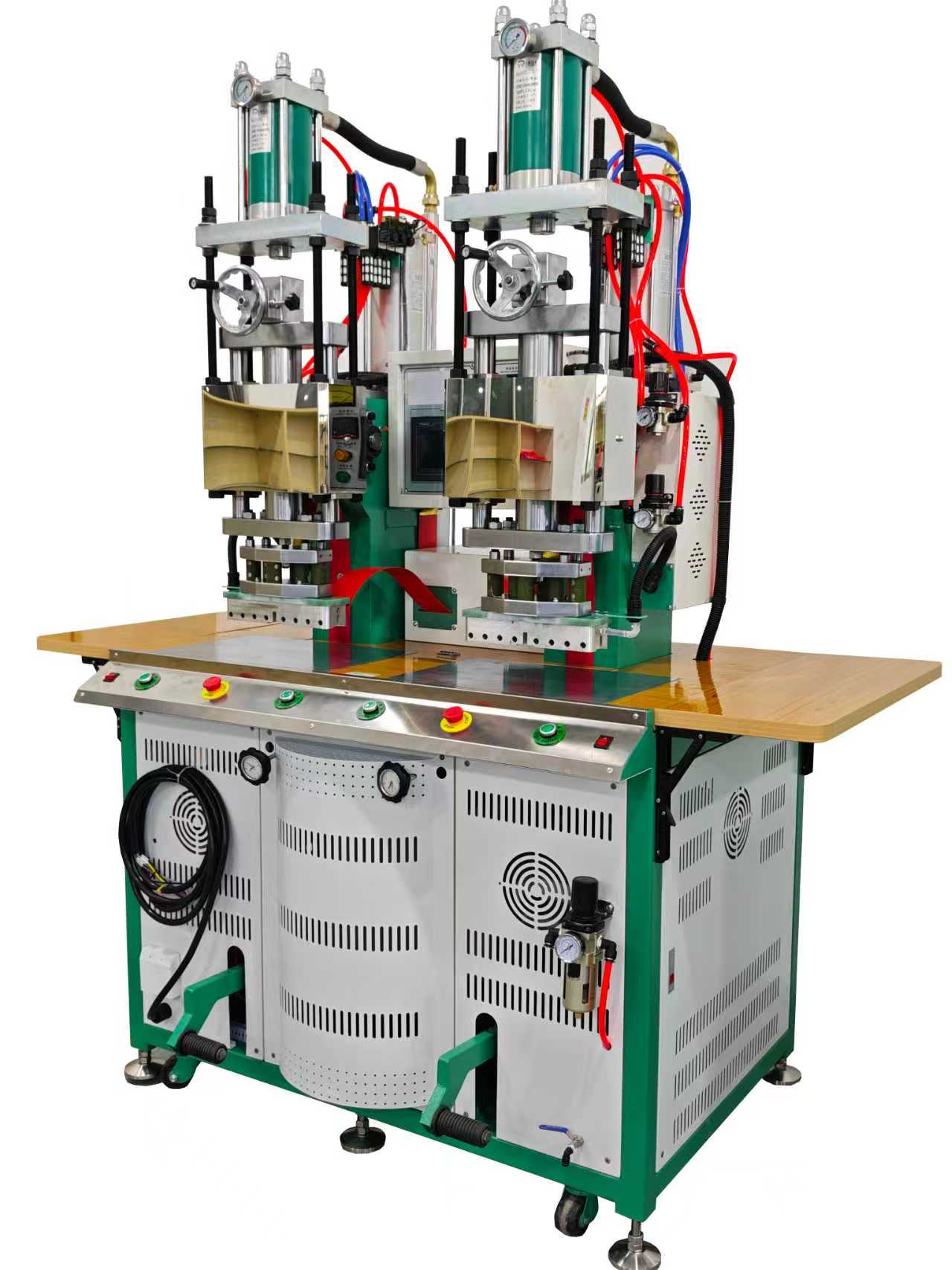
A double-head high frequency welding machine places two press heads on one production platform so a factory can alternate loading and welding, run two sequential operations or process matched parts. Pneumatic and hydraulic versions can both produce repeatable HF welds; the correct drive depends on required force, control response, tool size, part handling and the validated process window.
Terminology: High-frequency (HF) welding is also known as radio-frequency (RF) welding. In this guide, HF refers to the plastic welding process.
Double-Head HF Welder at a Glance
- Why two heads: alternate stations, separate operations or matched left/right components
- Pneumatic drive: clean, responsive and practical when regulated air pressure provides adequate force
- Hydraulic drive: suited to higher sustained force or larger tooling when the project justifies added hydraulic complexity
- Critical design: independent tooling alignment, controlled HF routing, station interlocks and safe operator access
- Proof: repeatability must be demonstrated at both heads with production-representative samples
What “Double-Head” Should Mean in a Technical Proposal
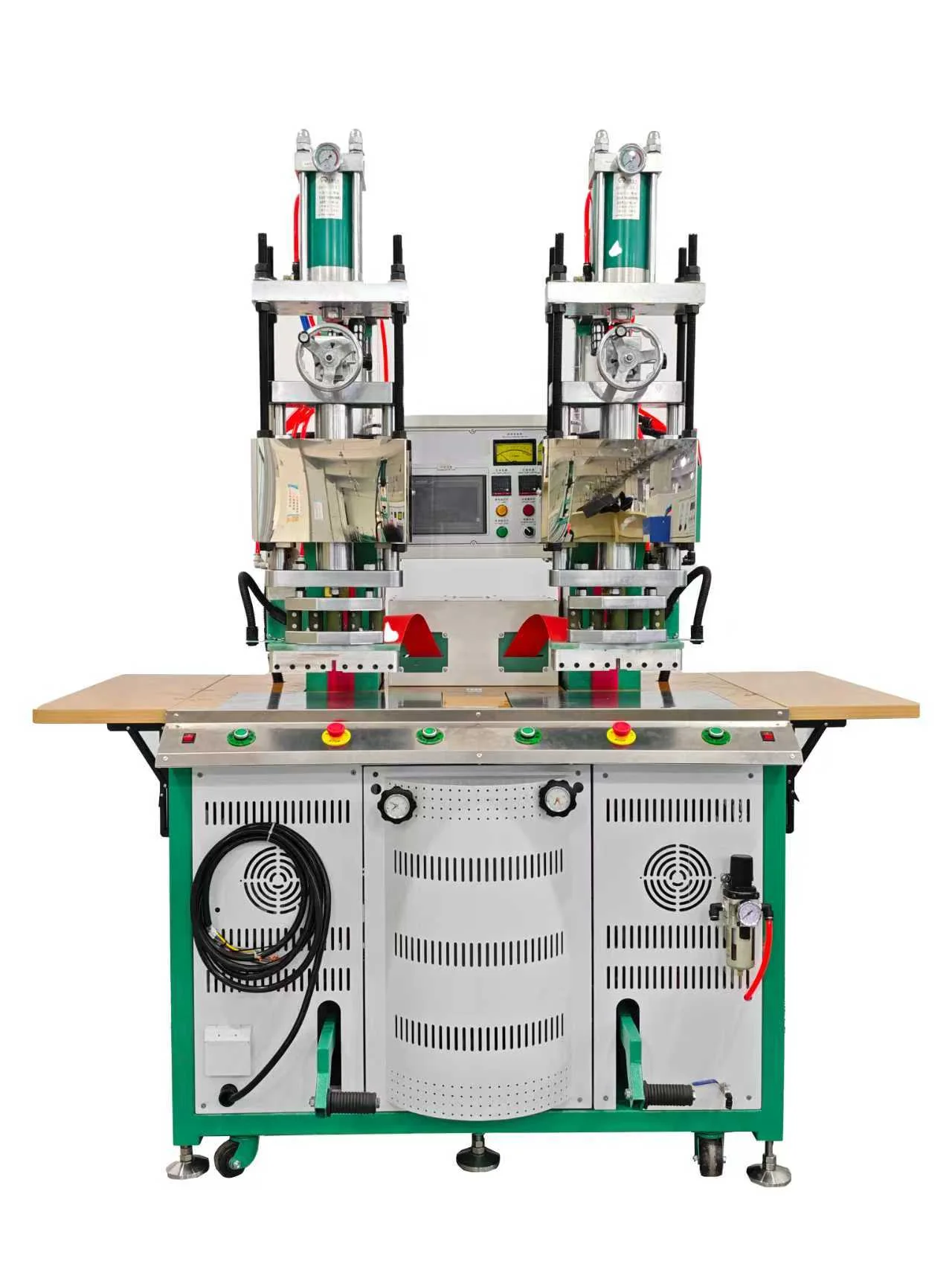
The label can describe several architectures. Two heads may share one HF generator and operate alternately, or a system may use independently controlled outputs. The heads may carry identical tools for capacity, different tools for two process steps, or mirrored tools for left- and right-hand parts. Buyers should not assume simultaneous HF output simply because two cylinders are visible.
The proposal should state how HF energy is routed, whether the heads can energize at the same time, which settings are independent and how the control prevents an operator from starting the wrong station. It should also define the usable table area, distance between heads, stroke, daylight and maximum approved electrode area.
Three Product Flows a Double-Head Machine Can Support
Alternating production
The operator loads one side while the other side is clamped and welded. After the cycle, the stations exchange roles. This reduces generator waiting time when manual loading is longer than the HF and cooling portion of the cycle. The actual improvement depends on balanced work content and safe access.
Sequential operations
One head can perform an embossing or preforming step and the second can complete welding or fusing. This is useful when a single tool would be too complex or when the two operations need different pressures and dwell times. Part transfer and orientation must be mistake-proofed.
Matched or mirrored parts
Footwear, bags and automotive trim often include left/right versions. Two dedicated tools can reduce changeover, but the HMI, barcode and fixture sensors should confirm that the correct component is loaded at each side.
Pneumatic Double-Head High Frequency Welding Machine
A pneumatic head converts regulated compressed air into press force. It can respond quickly, has a relatively clean drive package and is familiar to many maintenance teams. Force is influenced by cylinder area and actual air pressure, so the plant supply, regulator capacity, valve flow and pressure stability must be included in sizing.
Pneumatic drive is often suitable for footwear logos, coated-fabric components, stationery, smaller bags and similar work when the electrode area and pressure requirement are within the validated range. It is not inherently less accurate than hydraulic drive; repeatability depends on guides, stops, tooling, pressure regulation, valve timing and the complete machine frame.
Hydraulic Double-Head High Frequency Welding Machine
Hydraulic drive can provide high sustained force in a compact cylinder and can be practical for larger tools, deeper embossing or weld-and-cut applications. The design must manage oil temperature, filtration, leakage risk, pump noise and maintenance access. A hydraulic pressure reading is not the same as verified force at the tool; cylinder area, mechanical losses and tooling contact still matter.
Hydraulic is not automatically the premium choice. If the process needs modest force and fast responsive motion, pneumatic may be simpler. If high force, controlled approach or long pressure hold is central to the process, hydraulic may offer a better engineering margin. Sample trials should make the decision.
Plan the HF Process Around Both Stations
- Compare rotary and sliding-table layouts
- Review synchronous HF welding and cutting
- Understand 27.12 MHz tuning and spark protection
Send material data and a part drawing for a Jfortune process review.
Pneumatic vs Hydraulic: Buyer Comparison
| Decision area | Pneumatic | Hydraulic |
|---|---|---|
| Force source | Plant air and regulated cylinder pressure | Hydraulic power unit and controlled oil pressure |
| Typical strength | Fast response and simpler clean maintenance | Higher sustained force for demanding tools |
| Utility concern | Air quality, pressure stability and consumption | Oil condition, heat, filtration and leakage control |
| Selection rule | Use when proven force and motion needs fit the pneumatic window | Use when the validated process needs the hydraulic force profile |
HF Generator and Station Balance
A shared generator must be connected to only the intended head under a defined interlocked sequence. HF cables, bus bars, grounding and switching components should be designed for the approved output. The tuning arrangement must accommodate each tool without encouraging operators to compensate for a mechanical or material problem by excessive power.
For matched heads, verify the same recipe at both stations and compare results. If different tools are used, each needs its own qualified settings and acceptance limits. A central HMI should clearly show the active station, selected tool, HF stage, pressure status and any reason the cycle is inhibited.
Tooling Alignment on Two Heads
Each upper tool needs a guided, repeatable relationship to its lower fixture. Independent height adjustment may be required because electrode construction and material stack differ. Stops should prevent over-travel, and the tool mounting should make changeover possible without losing the approved alignment.
Where a shared table carries both fixtures, the frame must resist deflection and maintain level under the worst approved load. For cosmetic embossing, inspect depth and definition across the full tool. For weld-and-cut work, evaluate the cut edge, lower insulation and flash removal at every position.
Spark Protection and Process Discipline
A high-sensitivity arc protection system is especially important when two tools and more material handling create additional opportunities for contamination, misloading or damaged insulation. The protection should interrupt output, identify the affected station and require a controlled reset. Alarm history helps engineering distinguish occasional foreign material from a recurring tooling defect.
Daily checks should include electrode cleanliness, lower-board condition, ground straps, guards and pressure settings. Operators need a defined response to an arc event; repeatedly resetting the machine without inspecting the tool can turn a small defect into expensive damage.
Operator Safety for Alternating Stations
Alternating work areas can create confusion about which head will move next. The control system needs clear station indicators and must prevent head descent or table motion while a person can access the hazard. Depending on the layout, this may require two-hand controls, light curtains, fixed guards, interlocked covers or a combination supported by the risk assessment.
Emergency stops must remove hazardous motion and HF output in a defined way. Recovery after a guard opening, power interruption or emergency stop should not automatically resume the interrupted cycle. Destination-country electrical and machine-safety requirements belong in the technical agreement before design release.
Applications That Benefit from Two Heads
- Footwear uppers, logos, decorative panels and no-sew layered components.
- Bags, luggage panels, pockets, reinforcements and structured covers.
- Coated-fabric products requiring two weld shapes or sequential embossing.
- Automotive interior pads, covers and appearance-sensitive trim confirmed as HF compatible.
- Matched left/right components or two cavity families with frequent production changeover.
Suitability is based on the exact material and joint. A product category alone does not prove HF compatibility or determine whether two heads are economical.
Factory Acceptance Plan for Both Heads
Run a defined quantity at head A, head B and in the intended alternating sequence. Record recipe, pressure, cycle time, arc alarms and inspection results. The sample plan should include each cavity, tool position and part variant. Measure strength, leak performance, cut quality, embossed appearance or dimensions according to the product requirement.
Demonstrate tool changeover, recipe selection, wrong-part prevention and alarm recovery. Confirm utilities while both stations operate in the maximum intended sequence. Review wear parts, electrode maintenance, recommended spares and the method for reproducing approved tool height after service.
RFQ Information That Prevents Rework
- Explain whether the two heads are for capacity, sequential operations or left/right parts.
- Provide drawings for both tools and identify active electrode area.
- Send exact materials and production-representative samples.
- Define pressure-sensitive and cosmetic zones.
- State cycle target, staffing plan and required station balance.
- Specify pneumatic supply or hydraulic preferences only after force review.
- List safety, traceability, recipe and destination requirements.
Compare Two-Head Configurations with Your Actual Parts
Jfortune can evaluate pneumatic and hydraulic force needs, HF routing, tooling, operator balance and acceptance tests from your drawings and samples.
Frequently Asked Questions
Can both heads weld at the same time?
Only if the approved generator and HF distribution architecture are designed for simultaneous operation. Many double-head systems use one generator and alternate the heads. The proposal must state this explicitly.
Which drive is more repeatable?
Either can be repeatable when correctly sized and guided. Evaluate force stability, stops, alignment, controls and sample results rather than choosing from the drive name alone.
Does a double-head machine always double output?
No. Output depends on loading, HF time, cooling, table movement, operator balance, changeover and downstream operations. A time study should compare the complete cycle.
Can two different products run on the machine?
Potentially, if tooling, HF range, force, table space and safety controls support both. Each product needs a qualified recipe and mistake-proof selection.
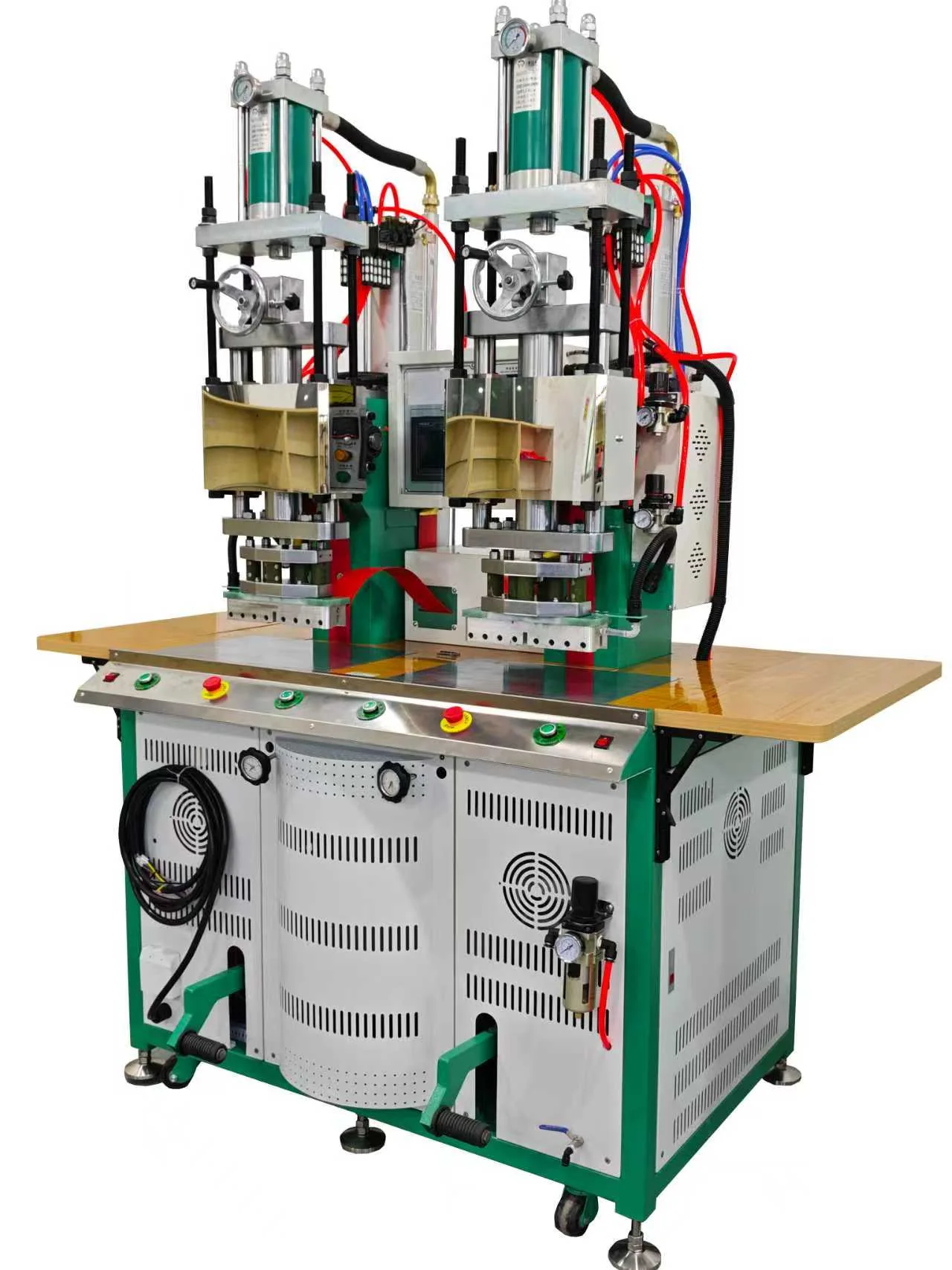
Engineering note: the pictured configuration illustrates a double-head HF press concept. Final generator arrangement, simultaneous capability, force, tooling and compliance scope are defined for each Jfortune project.
 EN
EN  DE
DE  ES
ES  PT
PT  RU
RU  JA
JA  IT
IT  AR
AR  KO
KO