
High frequency welding equipment uses a controlled radio-frequency electric field and pressure to heat compatible polar thermoplastics within the joint. The right machine is selected from the material, weld geometry, electrode area, loading method, cycle target and safety requirements – not from generator kilowatts alone.
Terminology: High-frequency (HF) welding is also known as radio-frequency (RF) welding. In this guide, HF refers to the plastic welding process.
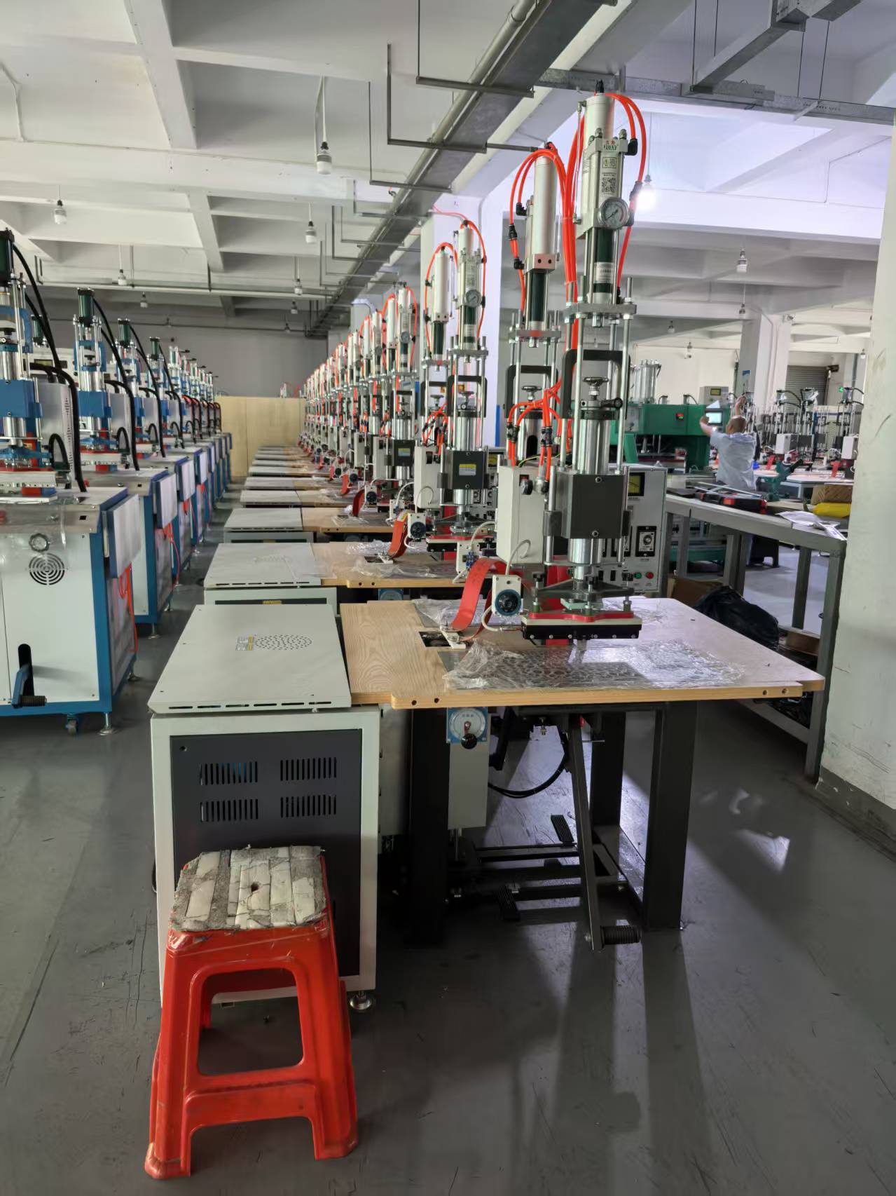
High Frequency Welding Equipment at a Glance
- Best fit: PVC, many polyurethane structures and other HF-responsive polar thermoplastics confirmed by trials
- Main variables: HF power, tuning, pressure, weld time, cooling time, electrode geometry and material condition
- Common layouts: single station, dual head, sliding table, rotary table and automated indexing systems
- Quality controls: recipe management, arc protection, pressure monitoring, part detection and sample-based acceptance
- Buyer priority: prove the process with the actual laminate, insert, coating and production-representative parts
What High Frequency Welding Does
High frequency welding, also called HF welding or dielectric welding, is different from a conventional hot press. An alternating electric field causes molecular movement in a compatible material. Heat is generated through the thickness of the joint while an electrode applies pressure. When the field stops, the joint remains clamped during a controlled cooling period so the fused area can stabilize.
This internal heating mechanism can produce a continuous sealed seam, a shaped embossed area or a weld-and-cut result, depending on the tool and material stack. Typical applications include inflatable products, medical and protective products, footwear components, bags, automotive trim, stationery, technical textiles and coated-fabric assemblies. Every application still requires material confirmation: two sheets that look similar may respond very differently because of resin formulation, coating weight, reinforcement, plasticizer, moisture or surface treatment.
Start with Material Compatibility, Not Machine Power
The first engineering question is whether the complete material stack couples effectively with the HF field. Send the exact production grade, thickness, color, backing, foam, printed layer, adhesive film and insert. A supplier should test the complete stack rather than a generic sample labelled only “PVC” or “PU.” Decorative films, recycled content and flame-retardant additives can change the heating response and the process window.
Polyethylene and polypropylene generally do not respond to HF energy in the same way as PVC. They may require another joining process, a specially engineered layer or a different material specification. A responsible proposal states the confirmed material combination and trial result instead of promising that one HF welder will join every plastic.
How to Size the HF Generator
Generator rating is only one part of sizing. The required output depends on the total active electrode area, weld width, material thickness, dielectric response, number of simultaneous welds and target heating time. A long narrow seam and a large embossed panel can require different tooling and tuning even when their outside dimensions are similar.
Jfortune reviews the drawing and estimates the active area before selecting a standard platform. A 15 kW, 27.12 MHz system is a common industrial configuration for larger sliding-table work, but it is not a universal answer. Smaller tools may run more efficiently on a lower-power generator; a large multi-cavity tool may need a different output stage or a staged cycle. The approved technical agreement should define rated output, working frequency, input power, supply voltage and the usable tool envelope separately.
Choose the Machine Architecture Around Material Flow
Single-station press
A single station is suitable for prototypes, low-volume work, small tools or operations where loading time is short. It has the simplest footprint and tooling arrangement, but the generator may wait while the operator unloads and reloads.
Sliding-table machine
A front/rear or left/right sliding table separates loading from the press area. The operator can prepare the next part while another station completes the HF cycle. The table must locate repeatably, protect hands during movement and keep cables, grounding straps and tooling clear through the full travel.
Dual-head or rotary system
Two heads can support two operations, two tools or alternating stations. A rotary table can add several indexed nests for loading, preforming, welding, cooling and unloading. These layouts improve flow only when the operator balance, table index time and downstream handling are engineered as one cycle.
Tooling Determines the Actual Weld
The electrode concentrates the HF field and applies the required pressure to the joint. Its profile defines seam width, embossed detail, cut line and local energy density. Tool flatness, edge radius, insulation, grounding and alignment influence both appearance and arc risk. For weld-and-cut work, the cutting edge and stop height must be controlled so the tool separates the flash without damaging the lower support.
The lower fixture should locate the part without stretching the material or marking a cosmetic surface. Replaceable insulating boards and wear components make maintenance easier. For multi-cavity work, pressure and field distribution must be checked across every cavity; accepting one good position does not prove the complete tool.
Build a Repeatable Process Window
A stable recipe controls more than weld time. Typical settings include pre-clamp delay, HF ramp or heating stages, tuning position, pressure, hold time and cooling time. The goal is a window that tolerates normal production variation, not a single “perfect” setting found on one ideal sample.
During trials, record settings and results for low, nominal and high material thickness. Evaluate seam peel or burst performance where relevant, visual appearance, dimensional change, flash, incomplete fusion and electrode marks. Save approved recipes in the HMI with controlled access. Operators should select a part number or tool number rather than manually reconstructing the process at every shift change.
Arc Protection, Shielding and Operator Safety
A sensitive arc or spark protection circuit should interrupt HF output quickly when an abnormal discharge is detected. It can reduce damage to the electrode and material, but it is not a substitute for clean tools, correct tuning, sound insulation and disciplined maintenance. The FAT should deliberately verify the detection and reset sequence under an agreed safe test method.
HF shielding, grounding and leakage control are engineering requirements. The final machine also needs a risk assessment covering moving tables, pneumatic or hydraulic pressure, hot surfaces where applicable, stored energy, electrical access and unexpected restart. Emergency stops, interlocked guards, light curtains or two-hand controls must be selected for the machine layout and destination-country requirements. Operators must never bypass these controls to shorten the cycle.
Controls and Data Worth Specifying
- PLC/HMI recipes linked to part, tool or work-order identification.
- Password levels for operators, process engineers and maintenance staff.
- Pressure, table-position, guard and part-presence interlocks before HF enable.
- Cycle count, alarm history, maintenance reminders and reject acknowledgement.
- Optional barcode validation and production-data export when traceability is required.
More data is not automatically better. Define which values determine acceptance, how long records must be retained and how a rejected cycle is contained. Controls should support the factory’s quality system rather than create an isolated dashboard no one uses.
Factory Acceptance Testing
A useful FAT uses production-representative materials and an agreed sample plan. Check every station and cavity, not only a hand-selected “golden” part. Confirm the approved recipe, changeover steps, cycle time definition, weld strength or leak requirement, cosmetic limits and gauge method. Include repeat starts after planned stops and reasonable material variation.
The FAT should also cover guarding, emergency stops, interlocks, alarm recovery, tooling removal, maintenance access, spare parts and documentation. Record utilities at the test condition, including electrical supply, compressed air and cooling needs. A signed acceptance record gives both buyer and manufacturer a clear baseline for site installation.
Information Jfortune Needs for a Reliable Proposal
- 2D/3D part drawings and the exact weld or embossing path.
- Complete material specifications, thickness tolerance and representative samples.
- Required seam strength, leak rate, appearance and dimensional criteria.
- Annual volume, shifts, target cycle time and operator plan.
- Preferred loading method, number of stations and changeover frequency.
- Destination voltage, frequency, plant standards, language and safety requirements.
- Traceability, barcode, network and data-retention expectations.
Send Your Material Stack and Weld Drawing
Jfortune can review the HF response, electrode area, press layout, tooling concept and acceptance plan before recommending high frequency welding equipment.
Application-Specific HF Welding Buyer Guides
- HF welding machine for medical products
- High-frequency welding for automotive interiors
- Synchronous high-frequency welding and cutting
- Rotary-table vs sliding-table HF welding machines
- 27.12 MHz HF tuning and spark protection
Send material data and a part drawing for a Jfortune process review.
Frequently Asked Questions
Is HF welding the same as a hot press?
No. HF welding generates dielectric heat within a compatible material under an alternating electric field. A hot press transfers heat from a heated platen or tool by conduction. Both apply pressure, but material compatibility, tooling and process controls differ.
Does a higher kW rating always weld faster?
No. Cycle time also depends on electrode area, material response, pressure, tuning, cooling, handling and the allowable process window. Oversizing without proper control can increase instability rather than improve output.
Why is the same recipe inconsistent between material batches?
Thickness, formulation, moisture, surface treatment, reinforcement and storage condition can change HF response. Record incoming-material data and qualify the recipe window across normal variation.
Can Jfortune quote from a product photo?
A photo supports an initial discussion, but a reliable quotation requires drawings, materials, weld geometry, quality criteria, production volume and destination requirements. Samples are strongly recommended for process trials.
Engineering note: final power, frequency configuration, tooling, cycle time and safety scope are project-specific and are confirmed only after Jfortune reviews samples and signs the technical agreement with the buyer.
 EN
EN  DE
DE  ES
ES  PT
PT  RU
RU  JA
JA  IT
IT  AR
AR  KO
KO